m105_1

m105_2
m105_3
IRIS TUTORIAL
Preprocessing of grey level images (2/2)
The Automatic preprocessing (2) command of Preprocessing menu make a full preprocessing. The result is a sequence of aligned images. In some situation it is usefull to reserve the registration to specifics distinct commands. Indeed, the registration of some type of images requires particular tools. It is the case in particular if the image contain few stars or on the contrary, too many stars.
The Automatic preprocessing (1) command of Preprocessing menu permit subtraction of the offset, of the dark and division by the flat-field to a sequence of images. But the result is a new sequence of unregistrered images only.
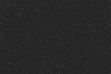
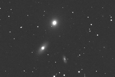
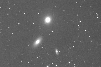
Consider the three raw frames of the Messier 105 field:
|
|
|
|
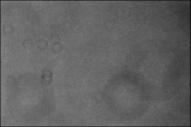
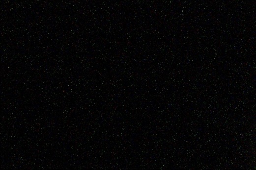
and the three associated master images:
|
|
|
|
That is the solution if an offset master is not available?
Do not panic! Two solutions...
Method 1
Load one of the science image:
>LOAD M105_1
Give to all pixels an identical value, the typical level of the offset in your numerical camera. Here for example>FILL 377
The current image is now filled with the value 377. Finally save this artificial offset master:
>SAVE OFFSET
Method 2
Note the format of the science images:
>LOAD M105_1
>INFO
The format of the in memory image is here 384 x 256 pixels.
Create a new black image:
>NEW 384 256
Fill
>FILL 377
and save
>SAVE OFFSET
I have not a flat-field image!
Do not panic (but it is never a good thing...)! Create an artificial flat-field with a constant level, for example the level 10000:
>LOAD M105_1
>FILL 10000
>SAVE
FLAT
Preprocessing
First, load the first image of the sequence to process, and define with the mouse an area which do not contain any major object and brilliant stars if possible. The width of this zone is approximately 100 to 200 pixels. This part of the image will be used to calculate the optimal dark image for minimizing the noise of final result (see further).
Then, open the dialog Automatic preprocessing (1) (of Preprocessing menu) and enter the parameters
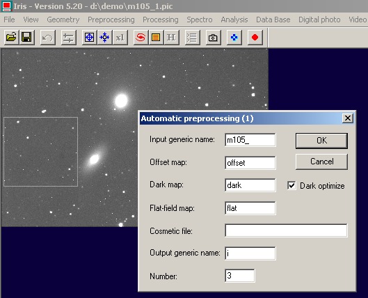
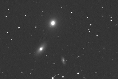
Click OK. The sequence i1.pic, i2.pic and i3.pic is created. These three images are preprocessed. For displaying the images, run:
>LOAD I1
>LOAD I2
>LOAD
I3
|
|
|
|
How to adjust the visualization thresholds of a sequence?
Iris preserves in the header of the images (PIC or FITS) the active visualization thresholds just before save operations. It is possible to modify these thresholds for all the sequence with command TH_CUT. For example:
>TH_CUT I I 1600 500 3
The new tresholds or I1, I2 and I3 images are (1600, 500).
You can run also the equivalent Threshold command of View menu:
Dark optimization
For long exposure imagery, one of the major difficulties during preprocessing is the dark current correction. This parasitic signal, due to thermal charges, is added to the signal produced by the observed objects. The problem is to suppress this noisy parasitic component because detectivity is affected.
A classic solution is to take an exposure of the science object with a given integration time, then take another exposure with the same integration time while placing the detector in total darkness. This last exposure is called the dark current map. This map is a characteristic for a given electronic detector. At first approximation, the thermal signal is proportional to the temperature of the detector and to the integration time. If the temparature of the detector is the same during science images and dark images acquisition, the correction is simple: the dark frame is directly subtracted to the science images.
This is, however, far from the ideal solution. In fact, this procedure implies that a dark current map must be taken after each image of the object is the temperature of the detector is not strictly controlled. This is very constraining when the exposure time is of several minutes or more.
Things seem to go better if the temperature of the CCD is perfectly stable. In this case, a priori only one map is necessary. It can be taken, for example, at the beginning of the observing session, and can be used to correct all the sciences images of a night. But If the exposure time is not the same between the dark map acquisition and the image to be processed, the dark map must be multiplied by a coefficient before the subtraction. This coefficient is the ratio between the exposure time of the image and the exposure time of the dark map.
Note that the dark map has its own noise and when the map is subtracted from the images, this noise is actually added to the science images. So, the dark map is normally a mean of numerous individual dark frames.
The efficient method:
- Take several (5 to 15) dark images with integration time similar to the science images (or longer). The detector temperature is also similiar (but not necessary strictly identical).
- For each exposure in darkness, another one with a minimal integration time is taken. This provides the offset map.
- For each of the dark images, subtract the corresponding offset map. Resulting images then contain only the thermal component of the signal.
- Add (arithmetic or median) all images of the previous step to obtain the final dark map. The sum adds the thermal contribution of each image, but averages the noise. This map can be considered caracteristic for a given detector (an instrumental constant).
- Subtract the computed master dark frame to each raw science images. The difficulty is in finding a multiplicative coefficient, to apply to the dark map, which will optimally corrects this image..
Iris solves the latter problem by using two approch.
- In the first one, Iris computes an optimal
coefficient applied to the dark map for minimizing the noise in a selected
area of the science image.
- In the second one, Iris computes an
optimal coefficient applied to the dark map for reducing the entropy of the
whole science image.
It is easy to test these two methods.
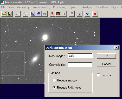
Load a raw science image, open the dialog Dark optimization of Preprocessing menu, select Reduce entropy and enter the name of your dark map (do not consider the cosmetic file for the moment) :
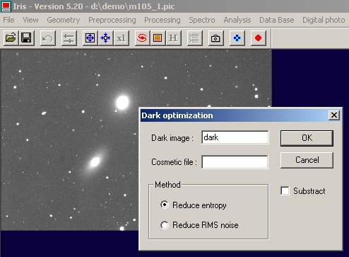
A coefficient value is returned, here 0.323. You can also invoque an equivalent console command:
>OPTE DARK
If the dark map is multiplied by this coefficient and if the result is subtracted from the science image, the entropy of the latter is minimized. It is often a good criteria for the dark optimization. The console procedure is for example:
>LOAD DARK
>MULT O.323
>SAVE
TMP
>LOAD M105_1
>SUB TMP 0
>SAVE I1
>LOAD M105_2
>SUB
TMP 0
>SAVE I2
>LOAD M105_3
>SUB TMP 0
>SAVE I3
or a more compact form
>LOAD DARK
>MULT O.323
>SAVE
TMP
>SUB M105_ TMP I 0 3
You can also check the Substract option of the Dark optimization dialog for judging the result.
The dark optimisation method by minimization of entropy is automatic if you select the option Dark optimization of the Preprocessing (2) dialog box. If this option is not selected, the coefficient is equal to the unity.
Many variations are possible. For example, separate the calculation of coefficent and the preprocessing steps:
>LOAD M105_1
>OPTE DARK
>LOAD
DARK
>MULT 0.323
>SAVE N
and finally preprocesses with these parameters
The Dark optimization dialog propose
also the noise reduction method. Before opening the dialog box it is necessary to select
a zone on the image (use the mouse), excluding if possible major astronomical
objects:
Iris return the value 0.319 (the difference is not significant here comparatively to the entropy method). The equivalent console command is:
>OPT DARK
The dark optimization by minimization of the noise is the method used in the Automatic preprocessing (1) command of Processing menu.
Note: the dark optimization procedure of Iris is compatible with color images (the R, G and B are processed separately). Example
|
|
|

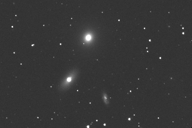
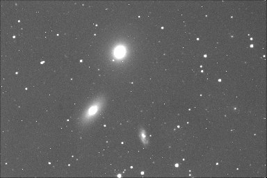
The
image after dark entropy optimization.
Cosmetic corrections
Cosmetic correction consists to remove bad individual pixels, bad columns or bad raws of an image. Very hot pixels are typical. These pixels saturates often long exposure images, so it is impossible to process this population of pixels by a simple subtraction of a dark map.
The cosmetic file is a text file which contain the list of the bad pixels, raws and columns. For example if the contains is
P  120 310
P    9 501
P  232 140
L  100   0
C   20   0
bad pixels are located at positions (120,310), (0,501), (232, 140). The line 100 is a bad line, and the column 20 is a bad column. Up to 2000 bad pixels can be defined in a cosmetic file. The extension of the file is obligatory ".lst". For exemple cosme.lst is a valid name.
The bad pixels (or column, or lines) are replaced by interpolation from surrounding good pixels.
The cosmetic file can be generated automaticaly for hot pixels. The appropriate command for identify hot pixels is FIND_HOT. Load the reference dark frame:
>LOAD DARK
then
>FIND_HOT COSME 1000
All pixels which have a value above the threshold 1000 will be marked as bad. Iris find here 38 hot pixels - a typical number for this type of images. The coordinates of the bad pixels are stored in the cosme.lst file:
You can of course give another name for the cosmetic file
>FIND_HOT BAD 1000
Try successive values for the threshold. 10 to 100 hot pixels is standard for a CCD images (the result is depending of the image size, of detector technology, on temperature, etc.). The cosmetic map is attached to a given detector and it is a constant for this detector (but remember, refresh the data regularly).
To take into account cosmetic file during preprocessing, enter a valid file name in the corresponding item of dialog
The Dark optimization dialog box accept also a cosmetic file: the flagged pixels are excluded for the computation of the optimized dark coefficient.
You can also applied a cosmetic correction as an indepedant operation with COSME command. For example, if the cosmetic file name is cosme.lst, load the image to correct, then type:
>COSME COSME
or if the name is bad.lst
>COSME BAD
You can applied cosmetic correction to a sequence of images. Open the Cosmetic correction dialog of Preprocessing menu, enter the field, then OK:
or
>COSME2 I I COSME 3